

Opening the RF StateSide Projects
RF StateSide is beginning a project-by-project transition to public engineering references, open-source software, and open hardware so others can use, study, continue, and improve the work.
Blog 10/10/2026 by Webmaster
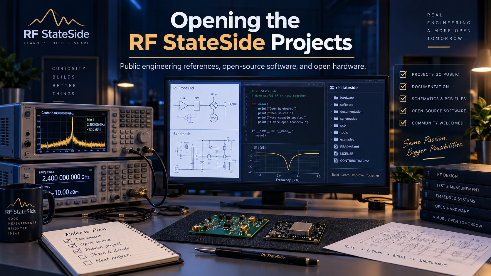
RF StateSide is entering a new chapter.
After many years of developing RF, embedded, marine-electronics, and software projects, I am now retired from the product-sales side of RF StateSide. Rather than allowing these projects to simply remain private or disappear over time, my goal is to make them available so others can study them, build on them, continue their development, and improve them.
The RF StateSide website has already begun that transition. The store is no longer the focus of the site. RF StateSide is now centered on engineering projects, software and hardware development, technical documentation, downloads, and community discussion.
A project-by-project public release
The existing RF StateSide projects are being reviewed individually before publication. Each project has its own history, dependencies, documentation, hardware files, software, firmware, and licensing considerations, so there will not be a single bulk release.
The goal is to prepare each project as a Public Engineering Reference — AS-IS, with reasonable best-effort cleanup, documentation, provenance and licensing review, and release validation.
The current planned release sequence is:
- RayCoupler — including the 200 W and 2 kW designs
- RayRigAntSw
- RayRailSwSense
- RayNmeaSimulator
- RayPowerMeter
- MercuryLuxPc
- RayWn2Meter
- RaySspaController
- RayVessel
- RayEltekController
This order reflects the current audits and relationships between the projects. It may evolve if additional historical material or technical dependencies are discovered during release preparation.
What will be published?
The exact contents will vary by project, but the intent is to make useful engineering material available wherever rights and provenance allow. Depending on the project, that may include:
- source code and firmware;
- editable hardware design files;
- schematics and PCB layouts;
- BOMs and fabrication files;
- desktop applications and utilities;
- release packages;
- build and configuration documentation;
- technical notes and project history.
Some projects are software-only, some hardware-only, and several combine hardware, firmware, and desktop software.
A project will not be labeled Open Source or Open Hardware until its individual audit and publication work are complete.
BrickSuite is already showing the direction
BrickSuite is already publicly available as an open-source project and represents much of the direction I want RF StateSide to take going forward: an actively developed project with public source code, documentation, downloadable releases, and continued development.
The other RF StateSide projects will follow one at a time as their release preparation is completed.
Follow the progress
This Blog will serve as the ongoing record of the transition.
I will add Posts as projects move through their audits and preparation, when significant issues are resolved, and when repositories and design files become publicly available.
There are no fixed release dates. I would rather publish each project carefully and accurately than promise a schedule that does not reflect the actual work involved.
RF StateSide remains active
Although I am retired from the previous product-sales focus, RF StateSide is not shutting down.
I continue to develop engineering projects, including BrickSuite, and remain open to interesting opportunities involving technical collaboration, consulting, engineering work, licensing discussions, and related projects.
The goal is simple: preserve the work, make it useful, and give others the opportunity to take these projects further.
I’m looking forward to sharing them.
RayRailSwSense Is Now Public — Open Hardware for DC Rail Switching and Sensing
Post 10/12/2026 by Webmaster
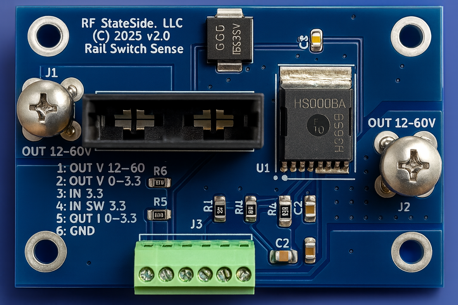
RayRailSwSense Is Now Public
Today I’m releasing RayRailSwSense as the third project in RF StateSide’s ongoing public engineering-reference effort, following RayCouplers and RayRigAntSw.
The complete engineering reference is now publicly available on GitHub:
https://github.com/RFStateSide/RayRailSwSense
RayRailSwSense is a high-side DC rail switching and sensing board designed to provide switched power together with rail-voltage and current/diagnostic information for an external controller.
The published design is based on the BTH50030 high-side switch and includes a fuse, transient-suppression components, filtering, voltage sensing, and current/diagnostic sensing.
It is being published under the CERN-OHL-P v2.0 hardware license as a:
Public Engineering Reference — AS-IS
What is included
The repository includes the engineering material needed to study, reproduce, modify, and continue developing the design, including:
- editable KiCad schematic and PCB sources;
- Bills of Materials;
- manufacturing files;
- assembly and integration documentation;
- historical design and test information;
- known limitations;
- licensing and provenance documentation;
- public-release audit material.
The historically tested BTH-based population used the BTH500301LUAAUMA1, a 2 kΩ current-sense resistor, a Murata BLM31PG121SN1L ferrite bead, and an automotive-style fuse.
An alternative BTH50015 population is documented in the repository, but it was not independently validated as a separate hardware configuration.
Current and voltage sensing
One important goal of this release is to document the design without turning component specifications into guaranteed board ratings.
For the historically tested BTH50030 population with the 2 kΩ sense resistor, the documented current-sense relationship is approximately 58.8 mV/A nominal.
That is a calculated nominal relationship—not a measured calibration guarantee.
The current/diagnostic output also should not be treated as a universally safe 0–3.3 V ADC signal. Under device diagnostic or fault conditions, the sense voltage can rise above the normal controller input range.
An external receiving circuit should therefore be designed with appropriate protection, scaling, clamping, and fault handling.
The six-position controller interface
The published J3 interface provides:
- Raw switched Vout
- Divided Vout
- External 3.3 V input
- Switch control
- Current/diagnostic sense
- Ground
Two details are especially important for anyone integrating the board.
J3 pin 1 is the raw switched rail voltage. It is not a logic-level signal.
J3 pin 3 is an external 3.3 V input. It is not a regulated 3.3 V output generated by RayRailSwSense.
The repository documents the electrical interface and should be reviewed carefully before connecting the board to another controller.
Historical integration
RayRailSwSense was historically fabricated and tested as part of RF StateSide systems, including integration with RaySspaController and RayPowerMeter.
That provides useful evidence that the hardware concept and historical BTH implementation operated successfully in actual system use.
However, that history should not be interpreted as proof of universal controller compatibility.
In particular, historical RaySspaController connector revisions do not have an identical straight-through pin assignment. A straight-through six-wire cable should not be assumed safe or compatible without first checking the exact controller revision and pinout.
Earlier design history
RayRailSwSense also had an earlier implementation based on the LTC7001 and INA240.
That board was physically manufactured and populated. During assembly, a Q1 footprint pin-assignment issue was discovered, and Q1 was installed in the corrected physical orientation. The board was subsequently operated with RaySspaController.
That earlier design is preserved as part of the project’s engineering history, but it is not the build source for the current BTH-based release.
Historical hardware and the current release package
As with the first two RF StateSide hardware releases, there is an important distinction between historically tested hardware and the exact manufacturing package published today.
The BTH-based RayRailSwSense design was physically fabricated, populated, and tested historically.
The current prepared P2-prep-01 manufacturing package brings the released engineering source and manufacturing outputs into a consistent public-reference state.
However, P2-prep-01 has not itself been refabricated and physically tested as that exact revision.
Historical operating experience is therefore valuable engineering evidence, but it is not direct acceptance testing of the newly prepared manufacturing outputs.
Anyone building RayRailSwSense should perform their own inspection, electrical verification, thermal evaluation, and system testing.
About voltage and current ratings
Earlier RF StateSide descriptions presented RayRailSwSense using simplified 25 A / 50 A and broad voltage-range labels.
Those labels have intentionally been removed from the public engineering reference.
The actual usable voltage and current envelope depends on the complete implementation, including:
- the installed high-side switch;
- PCB copper and interconnects;
- fuse and fuse holder;
- thermal conditions;
- duty cycle;
- wiring and connectors;
- transient environment;
- controller/interface circuitry.
Component ratings should not be interpreted as a guaranteed complete-board continuous-current or operating-voltage specification.
The public repository documents the known constraints so builders can evaluate the design for their own application.
Why release it AS-IS?
The goal of these releases is to preserve useful engineering work and make it available for others to study and continue—not to present historical projects as newly certified commercial products.
Publishing RayRailSwSense as a Public Engineering Reference — AS-IS means documenting:
- what was built;
- what was historically tested;
- what was calculated;
- what was changed;
- what remains unverified;
- and where independent engineering judgment is required.
Others are welcome to study the design, build it, test it, modify it, adapt it, and improve it.
No commercial certification or guaranteed voltage, current, thermal, or sensing performance is claimed.
The third RF StateSide public release
RayRailSwSense is now the third completed release in the RF StateSide project-publication effort:
- RayCouplers
- RayRigAntSw
- RayRailSwSense
The next project currently planned in the release sequence is RayNmeaSimulator.
As before, there are no fixed publication dates. Each project will be released when its engineering sources, documentation, licensing, provenance, and limitations are ready to be presented accurately.
Explore RayRailSwSense
The complete engineering reference is available here:
https://github.com/RFStateSide/RayRailSwSense
If you build the board, integrate it with another controller, characterize its performance, identify a limitation, or develop an improvement, I’d be interested to hear what you learn.
Making that kind of continued engineering possible is the reason these projects are being released publicly.
RayRigAntSw Is Now Public — Open Hardware for RF Switching
Post 10/11/2026 by Webmaster
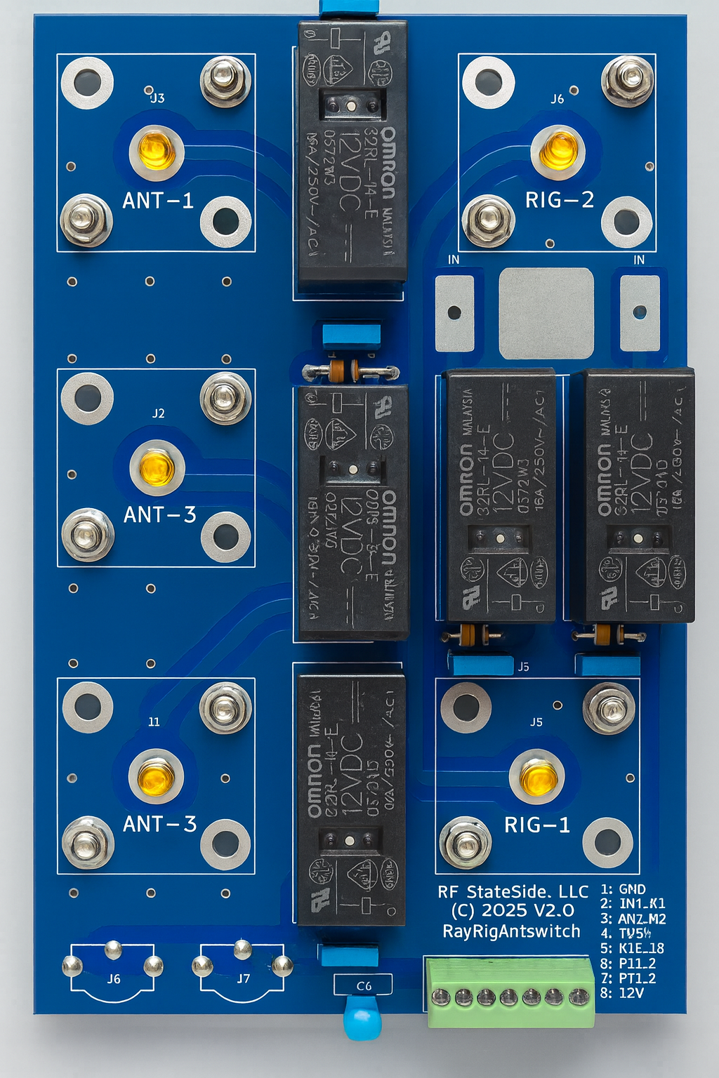
RayRigAntSw Is Now Public
Today I’m releasing RayRigAntSw as the second project in RF StateSide’s ongoing public engineering-reference effort, following the release of RayCouplers.
The complete engineering reference is now publicly available on GitHub:
https://github.com/RFStateSide/RayRigAntSw
RayRigAntSw is a through-hole RF relay board designed to provide switching between two radio paths, three antenna paths, and an amplifier/bypass path.
The board uses five 12 V SPDT relays and provides an eight-position controller interface for relay control, PTT connections, ground, and 12 V power.
It is being published under the CERN-OHL-P v2.0 hardware license as a:
Public Engineering Reference — AS-IS
What is included
The repository includes the engineering material needed to study, reproduce, modify, and continue developing the design, including:
- editable KiCad schematic and PCB sources;
- Bills of Materials;
- manufacturing files;
- assembly and integration documentation;
- historical construction information;
- known limitations;
- licensing and provenance documentation;
- public-release audit material.
The relay-coil suppression network uses 1N5819 flyback diodes and 10 nF capacitors. The relay coils are intended to be driven by suitable external low-side drivers, rather than directly from MCU GPIO pins.
Controller responsibilities
RayRigAntSw is the RF switching hardware itself. It does not contain the higher-level controller logic required to operate an RF station safely.
Functions such as:
- transmitter arbitration;
- relay sequencing;
- transmitter inhibit;
- amplifier timing;
- hot-switch prevention;
must be handled by the external controller and the overall station design.
The two PTT connections on the board are routed interface connections; the PCB itself does not provide simultaneous-transmit protection or arbitration.
Historically, RayRigAntSw was integrated and operated with the RaySspaController system, providing useful evidence that the original hardware was fabricated, assembled, and used as part of a working RF control system.
Historical hardware and the current revision
There is an important distinction between the historically tested boards and the manufacturing files being released today.
The original RayRigAntSw boards were fabricated by PCBWay, assembled, and operated successfully. Those historical boards contained a known D1–D5 diode polarity-marking error in the PCB artwork.
The diodes on the working assemblies were installed with the correct electrical polarity despite the incorrect markings.
The current CAD corrects that historical marking error.
However, the newly prepared P2-prep-01 manufacturing revision included in this public release has not itself been refabricated and physically tested as that exact revision.
The historical operating experience therefore provides useful engineering evidence, but it should not be treated as direct physical validation of the newly generated manufacturing package.
Anyone building the board should perform their own inspection, electrical verification, and RF testing.
Why release it AS-IS?
As with RayCouplers, the goal is not to present an older engineering project as a newly certified commercial product.
The goal is to preserve the design work and make it available so others can:
- study it;
- build it;
- test it;
- modify it;
- adapt it to other station-control systems;
- identify problems;
- improve the design.
That is the purpose of the Public Engineering Reference — AS-IS designation.
The repository documents what is known, what was historically fabricated and tested, what has since been corrected, and what still requires independent validation.
No commercial certification or guaranteed RF performance is claimed.
The second RF StateSide public release
RayRigAntSw follows RayCouplers as the second completed release in the RF StateSide project-publication effort.
The next project currently planned for release preparation is RayRailSwSense, with the remaining RF StateSide hardware and software projects following as their audits and documentation are completed.
There are no fixed publication dates. Each project will be released when its engineering sources, documentation, licensing, provenance, and known limitations are ready to be presented accurately.
Explore RayRigAntSw
The complete engineering reference is available here:
https://github.com/RFStateSide/RayRigAntSw
If you build the board, integrate it into another control system, test it, modify it, or find something that can be improved, I’d be interested to hear what you learn.
The goal of releasing these projects is to make the original engineering work useful beyond its original development—and give others a solid starting point for whatever they build next.
For the form, I’d mark this Published, but I would not make the Post itself separately Featured; the parent Opening the RF StateSide Projects Blog already provides the featured umbrella for the release program.
RayCouplers Is Now Public — Our First Open-Hardware Engineering Reference
Post 10/11/2026 by Webmaster
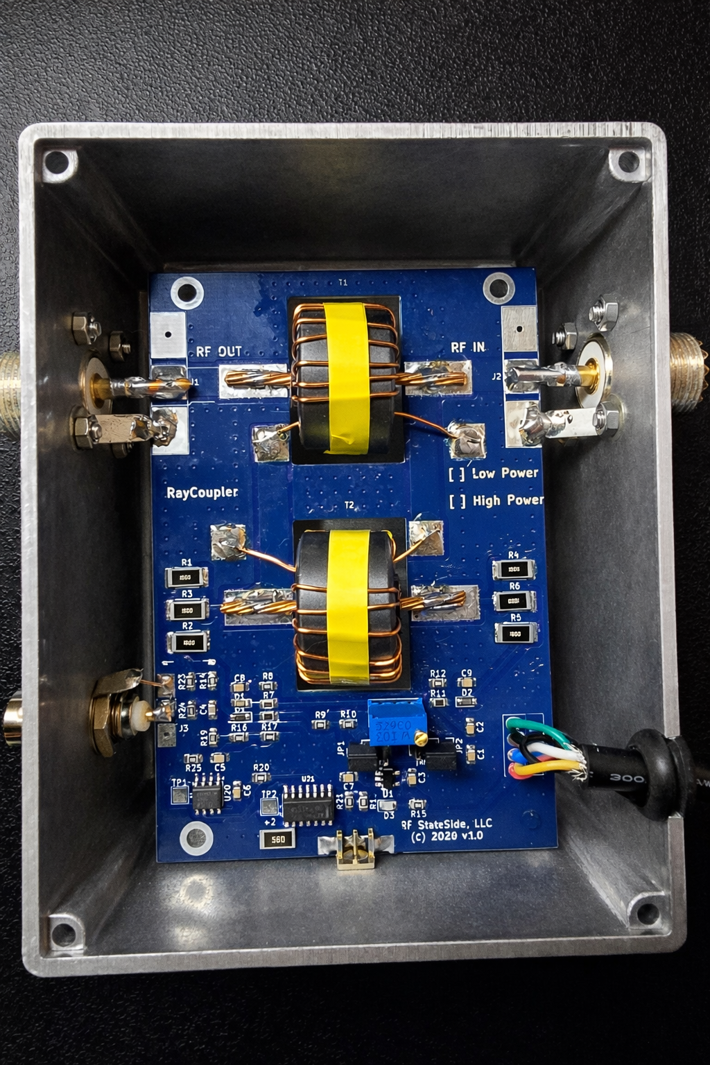
RayCouplers Is Now Public
Today I’m releasing RayCouplers as the first project in RF StateSide’s planned project-by-project public release effort.
The complete engineering reference is now publicly available on GitHub:
RayCouplers includes directional-coupler configurations intended for approximately 200 W and 2 kW RF applications. Both configurations use a common 70 × 102 mm PCB, with the primary differences coming from component population and transformer construction.
The repository is being published under the CERN-OHL-P v2.0 hardware license as a:
Public Engineering Reference — AS-IS
What is included
The public repository includes the material needed to study, reproduce, modify, and continue developing the design, including:
- editable KiCad schematic and PCB sources;
- Bills of Materials;
- manufacturing and fabrication files;
- construction and assembly documentation;
- 200 W and 2 kW configuration information;
- historical calibration and measurement information;
- licensing and asset-provenance documentation;
- the public-release audit and known limitations.
The 200 W configuration uses 16-turn transformers with one Fair-Rite #43 toroid per transformer. The 2 kW configuration uses 24-turn transformers with two taped #43 toroids per transformer. Both use Fair-Rite 5943001401 cores and 21 AWG high-temperature enameled copper winding wire.
The published detector design uses BAT42W SOD-123 Schottky diodes.
Historical measurements and the published PCB
There is an important distinction in the release documentation.
Earlier RayCoupler hardware was physically fabricated and used in real RF measurement systems. Historical calibration data and measurements from that hardware are included as useful engineering evidence. For example, one recorded sense-port measurement was approximately −58.23 dB at 14.426616 MHz.
RayCoupler was also used with the RayPowerMeter project as part of the RF measurement and monitoring system.
However, the newly curated P3-prep-01 SOD-123 manufacturing revision included in this public release has not itself been physically fabricated and RF-validated as that exact revision.
The historical results therefore should not be interpreted as guaranteed performance for every newly manufactured board. Anyone building the design should perform their own inspection, calibration, and RF validation.
Why release it AS-IS?
My goal with the RF StateSide public-release effort is not to turn old engineering projects into newly certified commercial products.
The goal is to preserve useful engineering work and make it available so others can:
- study it;
- manufacture and test it;
- modify it;
- learn from it;
- adapt it to new applications;
- improve it and take the design further.
That is what Public Engineering Reference — AS-IS means for these releases.
The documentation describes what is known, what was historically tested, what has changed, and where limitations remain. There is no claim of commercial certification or guaranteed RF performance.
The first of ten planned releases
RayCouplers is the first completed release in the RF StateSide project-publication effort announced in Opening the RF StateSide Projects.
The next projects currently planned for preparation are RayRigAntSw and RayRailSwSense, followed by the remaining RF StateSide hardware and software projects as their audits and release preparation are completed.
There are no fixed publication dates. Each project will be released when its engineering files, documentation, licensing, provenance, and limitations are ready to be presented accurately.
Explore RayCouplers
The complete RayCouplers engineering reference is available here:
https://github.com/RFStateSide/RayCouplers
If you build one, test it, modify it, find an issue, or develop an improvement, I’d be interested to hear what you learn.
The purpose of releasing these projects is to give the work a life beyond its original development—and hopefully provide a useful starting point for whatever comes next.